The monitor is a self-contained model that observes the communication of the DUT with the testbench. At most, it should observe the outputs of the design and, in case of not respecting the protocol’s rules, the monitor must return an error.
The monitor is a passive component, it doesn’t drive any signals into the DUT, its purpose is to extract signal information and translate it into meaningful information to be evaluated by other components. A verification environment isn’t limited to just one monitor, it can have multiple of them.
The monitors should cover:
- The outputs of the DUT for protocol adherence
- The inputs of the DUT for functional coverage analysis
The approach we are going to follow for this verification plan is: sample both inputs, make a prediction of the expected result and compare it with the result of the DUT.
Consequently, we are going to create two different monitors:
- The first monitor, monitor_before, will look solely for the output of the device and it will pass the result to the scoreboard.
- The second monitor, monitor_after, will get both inputs and make a prediction of the expected result. The scoreboard will get this predicted result as well and make a comparison between the two values.
A portion of the code for both monitors can be seen in Code 6.1 and in Code 6.2.
1 2 3 4 5 6 7 8 9 10 11 12 13 14 15 16 17 18 19 20 21 22 | class simpleadder_monitor_before extends uvm_monitor; `uvm_component_utils(simpleadder_monitor_before) uvm_analysis_port#(simpleadder_transaction) mon_ap_before; virtual simpleadder_if vif; function new(string name, uvm_component parent); super.new(name, parent); endfunction: new function void build_phase(uvm_phase phase); super.build_phase(phase); void'(uvm_resource_db#(virtual simpleadder_if)::read_by_name (.scope("ifs"), .name("simpleadder_if"), .val(vif))); mon_ap_before = new(.name("mon_ap_before"), .parent(this)); endfunction: build_phase task run_phase(uvm_phase phase); //Our code here endtask: run_phase endclass: simpleadder_monitor_before |
Code 6.1 – Code for monitor_before
1 2 3 4 5 6 7 8 9 10 11 12 13 14 15 16 17 18 19 20 21 22 23 24 25 26 27 28 29 30 31 | class simpleadder_monitor_after extends uvm_monitor; `uvm_component_utils(simpleadder_monitor_after) uvm_analysis_port#(simpleadder_transaction) mon_ap_after; virtual simpleadder_if vif; simpleadder_transaction sa_tx_cg; covergroup simpleadder_cg; ina_cp: coverpoint sa_tx_cg.ina; inb_cp: coverpoint sa_tx_cg.inb; cross ina_cp, inb_cp; endgroup: simpleadder_cg function new(string name, uvm_component parent); super.new(name, parent); simpleadder_cg = new; endfunction: new function void build_phase(uvm_phase phase); super.build_phase(phase); void'(uvm_resource_db#(virtual simpleadder_if)::read_by_name(.scope("ifs"), .name("simpleadder_if"), .val(vif))); mon_ap_after= new(.name("mon_ap_after"), .parent(this)); endfunction: build_phase task run_phase(uvm_phase phase); //Our code here endtask: run_phase endclass: simpleadder_monitor_after |
Code 6.2 – Code for monitor_after
The skeleton of both monitors is very similar to the driver, except for Lines 4. They represent one of the existing UVM communication ports. These ports allow different objects to pass transactions between them. In the section 6.0.1 you can consult a brief explanation of UVM ports.
The monitors will collect transactions from the virtual interface and use the analysis ports to send those transactions to the scoreboard. The code for the run phase can be designed the same way as for the driver but it was omitted in this section.
The full code for both monitors can be found in the file simpleadder_monitor.sv.
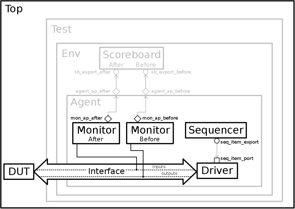
The the state of our verification environment after the monitors can be consulted in Figure 6.1.
 Figure 6.1 – State of the verification environment after the monitors
In chapter 4, it was mentioned that transactions are the most basic data transfer in a verification environment but another question arises: how do transactions are moved between components? We have already talked about TLM before when we were designing the driver. The way the driver gets transactions from the sequencer, it’s the same way the scoreboard gets them from the monitors: through TLM.
TLM stands for Transaction Level Modeling and it’s a high-level approach to modeling communication between digital systems. This approach is represented by two main aspects: ports and exports.
A TLM port defines a set of methods and functions to be used for a particular connection, while an export supplies the implementation of those methods. Ports and exports use transaction objects as arguments.
We can see a representation of a TLM connection in Figure 6.2.
 Figure 6.2 – Port-export communication
The communication is very easy to understand. The consumer implements a function that accepts a transaction as an argument and the producer calls that very function while passing the expected transaction as argument. The top block connects the producer to the consumer.
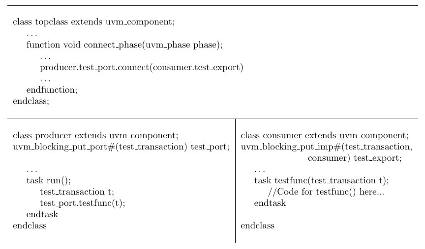
A sample code is provided in Table 6.1.
 Table 6.1 – Sample code for ports and exports
The class topclass connects the producer’s test_port to the consumer’s test_export using the connect() method. Then, the producer executes the consumer’s function testfunc() through test_port.
A particular characteristic of this kind of communication is that a port can only be connected to a single export. But there are cases when we might be interested in having a special port that can be plugged into several exports.
A third type of TLM port exists to cover these kind of cases: the analysis port.
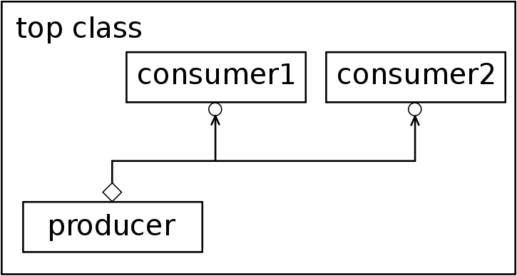
An analysis port works exactly like a normal port but it can detect the number of exports that are connected to it and every time a required function is asked through this port, all other components whose exports are connected to an analysis port are going to be triggered.
In Figure 6.2 it’s represented an analysis port communication.
 Figure 6.2 – Analysis port communication
The communication models mentioned here are part of Transaction Level Modeling 1.0. There is another variant, TLM 2.0, that works with sockets instead of ports, but they aren’t going to be mentioned in this training guide.
A brief summary of these ports and exports can be seen in Table 6.2.
 Table 6.2 – Sum up of TLM-1.0 ports
For more information about TLM, you can consult:
- Accellera’s UVM 1.1 User’s Guide, page 11.