Before understanding UVM, we need to understand verification.
Right now, we have a DUT and we will have to interact with it in order to test its functionality, so we need to stimulate it. To achieve this, we will need a block that generates sequences of bits to be transmitted to the DUT, this block is going to be named sequencer.
Usually sequencers are unaware of the communication bus, they are responsible for generating generic sequences of data and they pass that data to another block that takes care of the communication with the DUT. This block will be the driver.
While the driver maintains activity with the DUT by feeding it data generated from the sequencers, it doesn’t do any validation of the responses to the stimuli. We need another block that listens to the communication between the driver and the DUT and evaluates the responses from the DUT. This block is the monitor.
Monitors sample the inputs and the outputs of the DUT, they try to make a prediction of the expected result and send the prediction and result of the DUT to another block, the scoreboard, in order to be compared and evaluated.
All these blocks constitute a typical system used for verification and it’s the same structure used for UVM testbenches.
You can find a representation of a similar environment in Figure 2.1.
 Figure 2.1: Typical UVM testbench
Usually, sequencers, drivers and monitors compose an agent. An agent and a scoreboard compose an environment. All these blocks are controlled by a greater block denominated of test. The test block controls all the blocks and sub blocks of the testbench. This means that just by changing a few lines of code, we could add, remove and override blocks in our testbench and build different environments without rewriting the whole test.
To illustrate the advantage of this feature, let’s imagine a situation where we are testing a another DUT that uses SPI for communication. If, by any chance, we want to test a similar DUT but with I2C instead, we would just need to add a monitor and a driver for I2C and override the existing SPI blocks, the sequencer and the scoreboard could reused just fine.
UVM Classes
The previous example demonstrates one of the great advantages of UVM. It’s very easy to replace components without having to modify the entire testbench, but it’s also due to the concept of classes and objects from SystemVerilog.
In UVM, all the mentioned blocks are represented as objects that are derived from the already existent classes.
A class tree of the most important UVM classes can be seen in Figure 2.2.
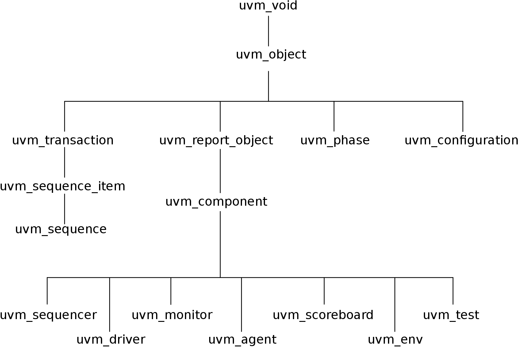
Figure 2.2: Partial UVM class tree
The data that travels to and from our DUT will stored in a class derived either from uvm_sequence_item or uvm_sequence. The sequencer will be derived from uvm_sequencer, the driver from uvm_driver, and so on.
Every each of these classes already have some useful methods implemented, so that the designer can only focus on the important part, which is the functional part of the class that will verify the design. These methods are going to addressed further ahead.
For more information about UVM classes, you can consult the document Accellera’s UVM 1.1 Class Reference.
UVM Phases
All these classes have simulation phases. Phases are ordered steps of execution implemented as methods. When we derive a new class, the simulation of our testbench will go through these different steps in order to construct, configure and connect the testbench component hierarchy.
The most important phases are represented in Figure 2.3.
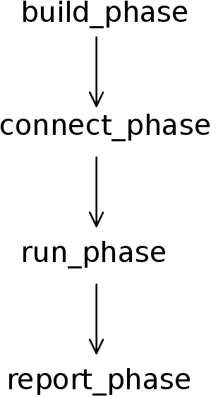 Figure 2.3: Partial list of UVM phases
A brief explanation of each phase will follow:
- The build phase is used to construct components of the hierarchy. For example, the build phase of the agent class will construct the classes for the monitor, for the sequencer and for the driver.
- The connect is used to connect the different sub components of a class. Using the same example, the connect phase of the agent would connect the driver to the sequencer and it would connect the monitor to an external port.
- The run phase is the main phase of the execution, this is where the actual code of a simulation will execute.
- And at last, the report phase is the phase used to display the results of the simulation.
There are many more phases but none of them are mandatory. If we don’t need to have one in a particular class, we can just omit it and UVM will ignore it.
More information about UVM phasing can be consulted in Verification Academy’s UVM Cookbook, page 48.
UVM Macros
Another important aspect of UVM are the macros. These macros implement some useful methods in classes and in variables. they are optional, but recommended.
The most common ones are:
- `uvm_component_utils – This macro registers the new class type. It’s usually used when deriving new classes like a new agent, driver, monitor and so on.
- `uvm_field_int – This macro registers a variable in the UVM factory and implements some functions like copy(), compare() and print().
- `uvm_info – This a very useful macro to print messages from the UVM environment during simulation time.
This guide will not go into much detail about macros, their usage is always the same for every class, so it’s not worth to put much thought into it for now.
More information can be found in Accellera’s UVM 1.1 Class Reference, page 405.
Typical UVM class
All this said, a typical UVM class will look a lot like the one described in Code 2.1.
1 2 3 4 5 6 7 8 9 10 11 12 13 14 15 16 17 18 19 20 21 22 23 24 25 26 27 | class generic_component extends uvm_component; `uvm_component_utils(generic_component) function new(string name, uvm_component parent); super.new(name, parent); endfunction: new function void build_phase(uvm_phase phase); super.build_phase(phase); //Code for constructors goes here end_function: build_phase function void connect_phase(uvm_phase phase); super.connect_phase(phase); //Code for connecting components goes here endfunction: connect_phase task run_phase(uvm_phase phase); //Code for simulation goes here endtask: run_phase function void report_phase(uvm_phase phase); //Code for showing simulation results goes here endfunction: report_phase endclass: generic_component |
Code 2.1: Code for a generic component
The code listed here, is the most basic sample that all components will share as you will see from now on.
SimpleAdder UVM Testbench
After a brief overview of a UVM testbench, it’s time to start developing one. By the end of this guide, we will have the verification environment from the Figure 2.4.
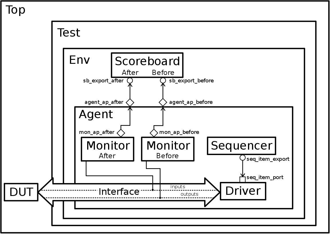 Figure 2.4: SimpleAdder Final Testbench
This guide will begin to approach the top block and the interface (chapter 3), then it will explain what data will be generated with the sequences and sequencers on chapter 4.
Following the sequencers, it will explain how to drive the signals into the DUT and how to observe the response in chapters 5 and 6 respectively.
Subsequently, it will explain how to connect the sequencer to the driver and the monitor to the scoreboard in chapter 7. Then it will show to build a simple scoreboard in chapter 8.
And finally, the test will be executed and analyzed.
The testbench can be run with the execution of a Makefile provided in the repository. As I mentioned previously, this Makefile uses Synopsys VCS but it should be easily modifiable to be executed with any HDL simulator.